Keyboard and Joystick port
Author
Publisher
Description
Keyboard:
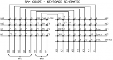
The Sam uses a membrane based keyboard much like the ZX Spectrum with flying ribbons back to the two Molex connectors on the Internal PCB to form the keyboard matrix.
Matrix data from http://velesoft.speccy.cz/samcoupe_keyboard-cz.htm
The keyboard membrane will, like the ZX Spectrum’s, degrade over time leading to breaks or fractures on the tracks on the flyleads. This can often be repaired with conductive paint, with replacement membranes or mechanical keyboard upgrades - see Keyboard Issues.
There were two forms of keyboard released: The original was beige keyed with a later version in grey with more textured finish, home key 'bumps' and a bolder font.
Joystick:
The joystick port also connects to this matrix but with a deviation from the standard Atari pin-out to allow two joysticks via a splitter by offering two different ground lines that drive different lines on the address bus, A12 for Joystick 1 (standard) and A11 for the second.
There was a Triple joystick interface add-on from Edwin Blink that allowed three joysticks to be connected.
Coupe DB9 connector (looking at rear of Coupé)
___________
\1 2 3 4 5/
 \6 7 8 9/
  -------
Joystick DB9 connector (looking at plug)
___________
\5 4 3 2 1/
 \9 8 7 6/
-------| Pin | Atari | Coupé |
|---|---|---|
| 1 | Joy Up | Joy Up |
| 2 | Joy Down | Joy Down |
| 3 | Joy Left | Joy Left |
| 4 | Joy Right | Joy Right |
| 5 | B Paddle/Tablet | 0v |
| 6 | Input Trigger/Fire | Fire |
| 7 | +5V | +5V |
| 8 | Gnd | Joystick 1 Gnd |
| 9 | A Paddle/Tablet | Joystick 2 Gnd |
Note: Most standard joysticks have no connection for pins 5 & 9 and only use +5V for auto-fire or additional circuitry.
Using the same port for both joystick connections is problematic as the shared nature of the connector coupled with making the joystick input appear as keyboard input made simultaneous movements on both joysticks interfere with each other.
Information from Andy Gale taken from the Sam Coupé Scrapbook
For a simple joystick doubler, you need two 9-way D plugs, and one 9-way D socket. Simply connect pins 1, 2, 3, 4, and 6 on the socket to exactly the same pins on BOTH plugs. Then connect pin 8 on the socket to pin 8 on the plug for joystick#1, and pin 9 on the socket to pin 8 on the plug for joystick#2 (NOT pin 9, notice). And that’s it.
HOWEVER! You will find that you get joysticks clashing with each other - if one joystick is pushing up-left and the other joystick is pushing up-right for example, then it appears that BOTH joysticks are pushing up, left and right all at the same time. How can you solve this? There are two methods: firstly you can try adding 5 diodes to each D plug: connect the anode to the direction pin on the joystick port (the socket) and the cathode to the relevant direction pin on the plug. Do this for every direction pin, and connect pins 8 and 9 on the joystick port as before. I’ve had limited success with this - one port worked but the other was temperamental. It might be better to use germanium diodes rather than silicon diodes since the voltage drop is lower. A far better solution is method two: use two hex tristate buffers with /OE fed from STROBEL1 or STROBEL2 (pins 8 and 9) on the joystick port. I shan’t explain how to do it here, but if you’re brave enough to give it a go then you can probably figure it out for yourself. Perhaps I’ll post the circuit diagram up somewhere… (pin 5 is Ov, and pin 7 is +5v)


