EDDAC
Release Year
Author
Publisher
Description
EDDAC stands for Edwin's Dual Digital to Analog Converter.
A stereo 8-bit DAC that plugs into the parallel port on the SAM élite, Comms Interface, External Drive Interface or the SPI.
The main application to utilise the EDDAC is the SAM MOD Player which can output 4 samples at 7-bit resolution each.
The schematics were originally published on Fred 51, instructions and diagrams to build are extracted below.
The design was produced into a consumer model called the SAMdac by Ben Versteeg.
Instructions
HOW TO BUILD THE EDDAC
Before wanting to build the EDDAC you will probably want to know what the EDDAC does. The EDDAC is simply two DAC (digital to analogue convertors) hooked up to SAM's parallel printer port and the lightpen/audio socket. What this gives you is the capability to output two 8-bit samples (one left, one right). With the right software (the SAM MOD player for EDDAC) you can output four 7-bit samples (two left, two right), allowing Amiga modules to be played at a much higher quality than via the soundchip. The soundchip could output samples at 4-bits, so the quality is 8 times better.
Who can build the EDDAC
Although you do not need to be an electronics mastermind to build this device, some soldering experience would be handy since it does get rather tricky at times. If you have no soldering experience you could ask someone else to build it for you (don't tell them it will take approximately four hours) or you could give it a go anyway. Before building my EDDAC I had literally no soldering experience, but now...
Since I know virtually nothing about circuit schematics and the like the instructions will have screens with components which look like the components and not the symbols.
What do you need
Before starting building it is recommended that you make sure you have all the bits and pieces that you need. There is nothing more frustrating than discovering that you are missing something to be able to continue.
2 * 74HC574 (this is a one byte chip)
1 * 74LS14 (this is an invertor chip)
18 * 20Kohm resistor, 1% tolerance (a few spares may be handy)
16 * 10Kohm resistor, 1% tolerance (a few spares may be handy)
2 * 1nF capacitor
3 * 100nF capacitor
1 * Printer connector (26 pin female IDC, BBC type)
1 * Audio DIN plug (5 pin male, look at back of SAM for form)
1 * Flat IDC cable (26 wires wide, approx 10 cm)
1 * Connecting wire
1 * Circuit board (thing with holes, approx 6 cm * 8 cm)
Plus you will need some free time, the first EDDAC I built took me eight hours, the second one, four.
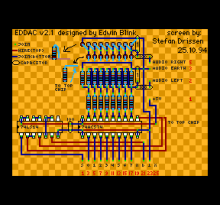
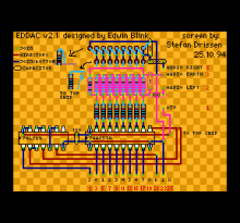
First of all lets have a look at the overall diagram. <Figure 1>
In principle you could build the whole board from that picture. But to help you along I will explain the steps to take. Each grid block is a hole in your circuit board.
The things that have to be done will be shown in pink on the screens that follow.
Step 1
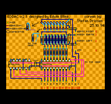
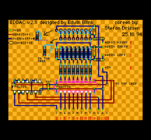
Cut the connecting wire to the right lengths so that you can put the wire onto the board as shown. The wire labelled to top chip can only be fixed at one point at the moment since it will be connected to the second 74HC574 which piggybacks on the first. Once your have put them into place (they probably will try to escape) go on to the next screen. <Figure 2>
Step 2
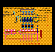
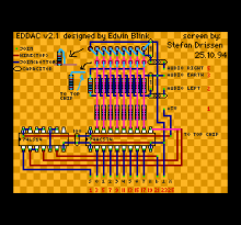
Put the 74LS14 chip one the board, this will jam some of the wires into place. Also put one 74HC574 chip in its place, this will also jam some of the wires into place. Be careful when placing the chips that you have the little indentation on the top of the chips pointing to the left. Also put the capacitor in its place.
Solder the chips into place and make the connections. The green dots show where two (or more) different parts are connected. <Figure 3>
Step 3
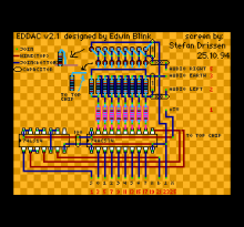
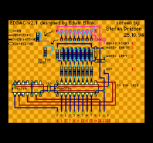
Solder eight 20Kohm resistors into place. How can you see the difference between a 20Kohm and a 10Kohm resistor? By looking at the colour bars. A 20Kohm has RED BLACK BLACK RED GOLD RED and a 10Kohm has BROWN BLACK BLACK RED GOLD RED. <Figure 4>
Step 4
Now you have to solder the other resistors and two capacitors in place plus make some connections (on the bottom of the board of course). Note that the leftmost resistor is a 20Kohm one, the other 8 are 10Kohm. The vertical capacitor is 1nF, the horizontal one is 100nF. <Figure 5>
Once you have completed this you may want to test half of the circuit before going on. Before you do this you will have to make the connections for the printer port and the audio socket.
Connect the printer connector to the flat cable, bearing in mind that the left edge has to be connected to the left of the board. Cut back the even numbers of the flat cable so that you can solder the odd numbers to the right places (see red numbers at bottom of diagram).
Using bits of connecting wire, solder the right connections from the board to the DIN plug. Don't forget to put the case of the DIN plug on the cable before soldering the second connection. For the first test you only need to solder the +5V, the audio earth and audio right.
Load up "EDDAC test" (see Fred 51 disk) to make sure that the first half is working properly. You can also load up the "SAM MOD player" and listen to the right half of a MOD via the EDDAC. This should give you the inspiration to go on and get the other half working.
Step 5
It is now time to piggyback the second 74HC574 chip. Carefully bend up the pins shown in pink. Put the chip on top of the first chip making sure that the pins of the top chip touch the pins of the bottom chip (except for the bent up pins - these must NOT touch). Now solder the top chip onto the bottom chip. <Figure 6>
Step 6
Connect the still loose wire end to the top chip. This is the chip select (just in case you're interested). Also solder in place the eight 20Kohm resistors. These are put in place standing up. One end is soldered to the pins of the top chip. <Figure 7>
Step 7
Put the other resistors in place (note that left most one is 20Kohm, the rest are 10Kohm) and solder them. Do the same for the capacitors. You can now connect the final wire of the audioplug to the left audio connection. <Figure 8>
And that was all! You can now test the second half of the circuit with the test program. If it all works fine then you can load up the SAM MOD player and listen to some decent music.
This info file (C) 1994 Stefan Drissen
The EDDAC design (C) 1994 Edwin Blink
The reason I wrote this is that we did not want to deprive the SAM world of this brilliant device. Producing the unit ourselves would be madness, so here it is. Since Edwin has emigrated to Thailand the rest is up to me...
Stefan Drissen 25.10.94

